CUSTOM MIRROR CELLS
by JP ASTROCRAFT
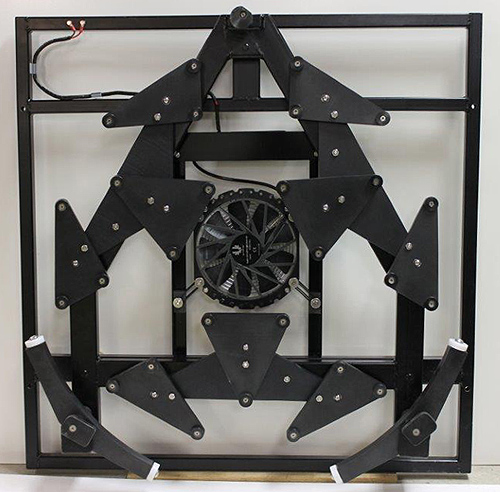
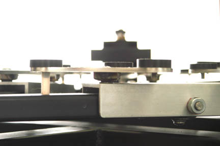
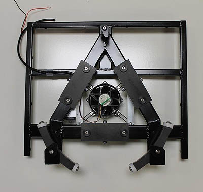
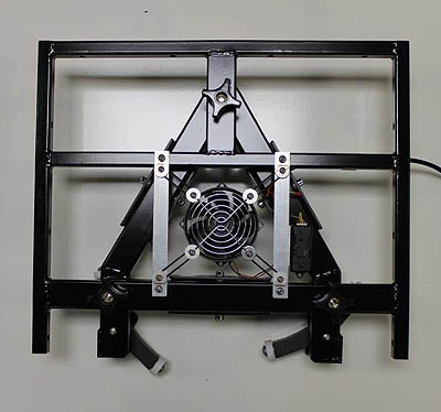
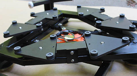
27-point cell for a 32" mirror with whiffletree edge support
Two-frame cell design - cells
done right
The JP Astrocraft mirror cell has been uniquely designed to provide optimum support and consistent alignment of your precision optic. The best materials are used, and the cell structure is built with strength and ultimate rigidity in mind, with the goal of zero collimation shift. I believe these are the most solid cells you can buy, and feature some of the best machining, craftsmanship, and attention to important details.
I build custom mirror cells in sizes from 8" and up. I have completed cells for mirrors larger than 1m (~40") in diameter, and have made parts for telescopes as large as 50". Please contact me for an estimate for your mirror cell project.
In my cells, the mirror sits in a frame and support framework that moves independently of the rest of the cell. The parts that touch the mirror - the triangles, edge supports, and retaining clips - all move with the mirror as collimation is adjusted.
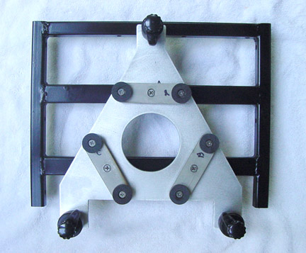
The separate frames can be seen in the image below left showing a smaller cell disassembled into its two main parts - on the left, the frame that bolts to the mirror box, and at right the frame that holds the mirror. The image below, right, shows the Bellevue washers that are used as springs between the two cell frames. This results in no deflection of the cell and no changing of alingnment with transport.
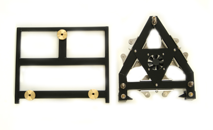
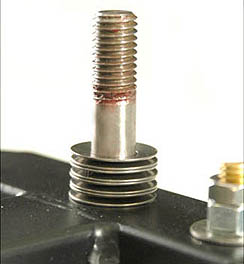
Separate frames (left images) and collimation bolt and Bellevue washers (right)
Edge Supports - designs backed up by real research
A sling is widely used to provide a simple, inexpensive, and effective edge support for alt-az telescopes. It suffers two problems:
The whiffletrees are seen at bottom left and right of the top image in this page, which shows a 32" mirror cell. Other manufacturers have since followed suit and adopted this type of edge support. I favor the whiffletree/roller edge support for cells up to 32".
Beyond that size, a cable sling may make sense, but only when mounted to the frame so that moves with the mirror. A cable sling, attached to the moving frame of the cell so it moves with the mirror as collimation is adjusted, can be seen in the 42" cell shown below.
54-point cell for a 42" f/3.75 mirror with cable sling edge support (photographed in shipping crate)
Other Features
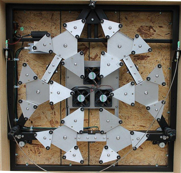
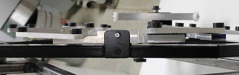
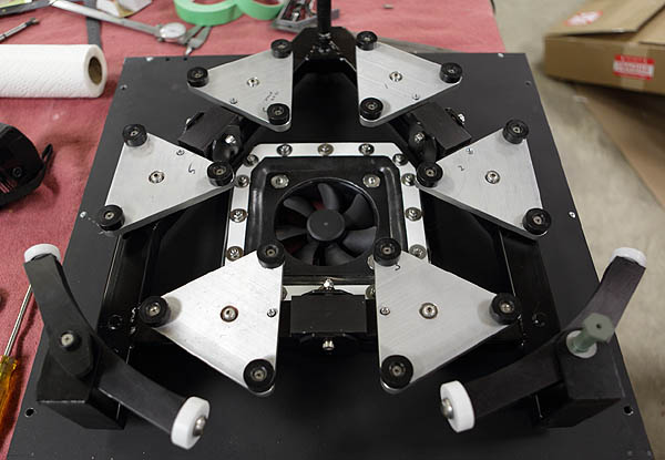
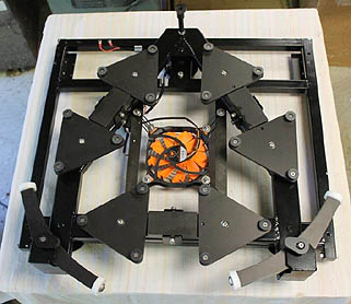
The larger cells feature spherical bearings at the support triangles to reduce slop in the pivot. The sweet sixteen cell uses channels that are shaft mounted for the levers, further controlling slop. This construction combination of pivots was found to show significantly less collimation shift as the scope is slewed, and results in a strong, easily collimated cell that resists collimation change while properly supporting the precision optic.
See image below. The shaft mounted aluminum channel and spherical bearing joint at the bottom of the triangle are visible. Also note the nylon triangle alignment pin extending downward from the triangle.
The JP Astrocraft mirror cell has been uniquely designed to provide optimum support and consistent alignment of your precision optic. The best materials are used, and the cell structure is built with strength and ultimate rigidity in mind, with the goal of zero collimation shift. I believe these are the most solid cells you can buy, and feature some of the best machining, craftsmanship, and attention to important details.
I build custom mirror cells in sizes from 8" and up. I have completed cells for mirrors larger than 1m (~40") in diameter, and have made parts for telescopes as large as 50". Please contact me for an estimate for your mirror cell project.
In my cells, the mirror sits in a frame and support framework that moves independently of the rest of the cell. The parts that touch the mirror - the triangles, edge supports, and retaining clips - all move with the mirror as collimation is adjusted.
The separate frames can be seen in the image below left showing a smaller cell disassembled into its two main parts - on the left, the frame that bolts to the mirror box, and at right the frame that holds the mirror. The image below, right, shows the Bellevue washers that are used as springs between the two cell frames. This results in no deflection of the cell and no changing of alingnment with transport.
Separate frames (left images) and collimation bolt and Bellevue washers (right)
Edge Supports - designs backed up by real research
A sling is widely used to provide a simple, inexpensive, and effective edge support for alt-az telescopes. It suffers two problems:
- If a sling becomes misaligned it will pull on and bend the optic. The initial sling alignment is critical and will change as the mirror is collimated with the typical sling cell. At worst, you are moving and tilting the mirror to collimate while the sling is fixed to the non-moving frame. In some cells, the sling can move to follow the mirror, but still may become non-parallel to the plane of the center of gravity of the mirror. Misalignment can also occur if the sling shifts during transportation or use.
- The sling does not provide precise lateral centering of the mirror. Sling stretch, sling anchor bolt flex, and tilt from using a equatorial platform cause the mirror to shift laterally causing loss of the required optical alignment, which is particularly important for fast optical systems.
The whiffletrees are seen at bottom left and right of the top image in this page, which shows a 32" mirror cell. Other manufacturers have since followed suit and adopted this type of edge support. I favor the whiffletree/roller edge support for cells up to 32".
Beyond that size, a cable sling may make sense, but only when mounted to the frame so that moves with the mirror. A cable sling, attached to the moving frame of the cell so it moves with the mirror as collimation is adjusted, can be seen in the 42" cell shown below.
54-point cell for a 42" f/3.75 mirror with cable sling edge support (photographed in shipping crate)
Other Features
The larger cells feature spherical bearings at the support triangles to reduce slop in the pivot. The sweet sixteen cell uses channels that are shaft mounted for the levers, further controlling slop. This construction combination of pivots was found to show significantly less collimation shift as the scope is slewed, and results in a strong, easily collimated cell that resists collimation change while properly supporting the precision optic.
See image below. The shaft mounted aluminum channel and spherical bearing joint at the bottom of the triangle are visible. Also note the nylon triangle alignment pin extending downward from the triangle.
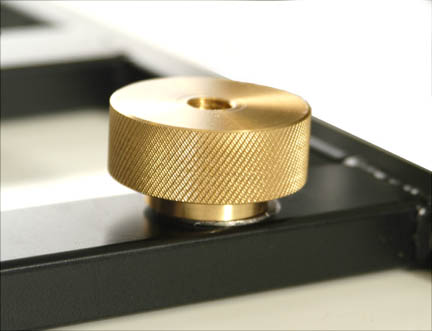
An optional brass collimation knob is shown below. It looks pretty, and adds a little balance for those big Naglers and Ethos eyepieces!
Other Mirror Cells
Six-point cell for a 10.25" mirror
Six-point
cell for a 14"
mirror, whiffletree edge support
18-point cell for a thin 20" f/3.0 mirror, whiffletree edge support
18-point cell for a 24" f/3.3 mirror, whiffletree edge support
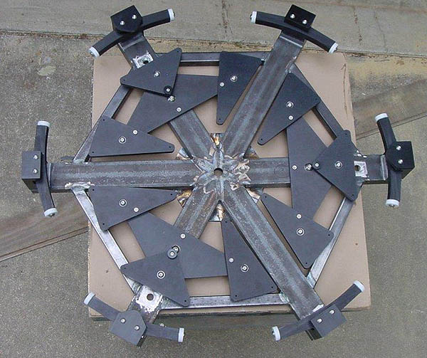
27-point
cell for 36" f/6.3
mirror, during construction. Multiple whiffletrees for
equatorial use (cell for Bigger Blue at Warren
Rupp Observatory).